ACCURATE.
SAFE. CLEAR.
SAFE. CLEAR.

Our logoStress transformations are graphically represented by Mohr's circle so it seemed appropriate to adopt this shape for our logo. Professor Mohr proposed the technique in 1882 whilst at Stuttgart Polytechnic.
The Transforming Stress Limited logo is the Mohr's circle representation of the three-dimensional state of stress at a point. |
|
|
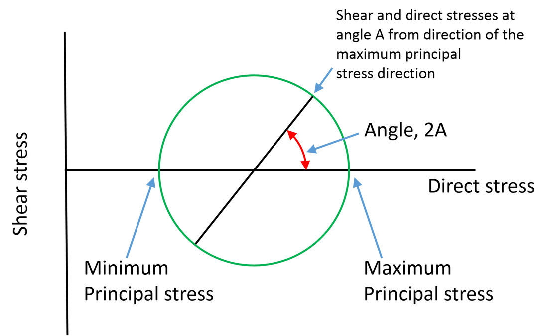
Mohr's circleThe two-dimensional version of Mohr's circle is familiar. Points are plotted with direct stress (x-axis) and shear stress (y-axis) coordinates. Principal stresses occur on planes that have no shear stresses, so, the maximum and minimum principal stresses are located on the x-axis.
The actual combination of shear and direct stresses is determined by a circle passing through the locations of two of the principal stresses and which is symmetric about the horizontal axis. Rotation in physical space by angle A is reproduced as angle 2A on the Mohr's circle (subtended at the centre of the circle). The coordinates of the point on the circle provide the combination of direct and shear stresses at the appropriate angle A (from the maximum principal stress in the case shown). |
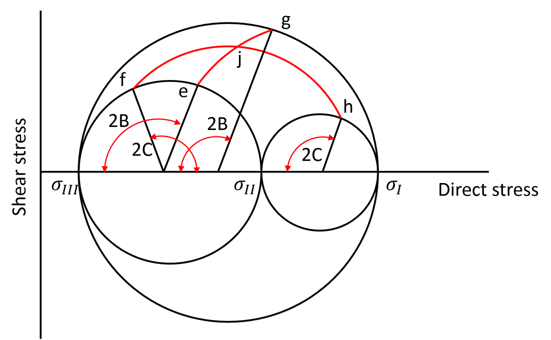
Mohr's circle in three dimensionsThere are three principal stresses, and each pair of principal stresses can be used to generate a single Mohr's circle for a single plane. But, what are the stresses on a cube that is not just a simple in-plane rotation away from a pair of principal stresses?
The Transforming Stress Limited logo provides one result for this case. All combinations of shear and direct stress for the three principal stresses which generate the logo are in the shaded region of the logo. But what about values for any particular case? For example, what if the angles between an axis and the minimum and mid principal stress directions are B, C respectively? The method is shown here. Create the points e, f, g and h, based upon angles B and C. Points f and h are on their respective Mohr's circles at angle 2C from the mid principal stress. Points e and g are at angle 2B from the minimum principal stress on their respective Mohr's circles Join points e and g with an arc, and then points f and h as shown. The arcs are parts of circles that are symmetric about the horizontal axis. The stress state on the plane defined by angles B and C is determined by the shear and direct values at the intersection of the two arcs (point j) as shown. |
|